Car Construction Part 1
In this lab, you will need to control an RC car using a DualShock 4 Controller. This will be done using a PCA9685 PWM driver board, and the NVIDIA Jetson TX2.
Unboxing and Setting up the Jetson
Your first task will be to unbox and setup the Jetson. You will need an HDMI monitor and an HDMI cable in order to use the board. The Jetson will be on a carrier board on the top of the box. Inside the box, you should find two black antennas, a power brick, a microUSB to USB male-male cable, and a white microUSB to USB adapter. Screw the antennas into the Jetson Carrier Board in order to get WiFi Access. Then plug the board into the power brick, and monitor. Press the red power button labeled “pwr” on the carrier board. You should be greeted by the Ubuntu 16.04 login screen. The account name will be nvidia, and the password to login is also nvidia. 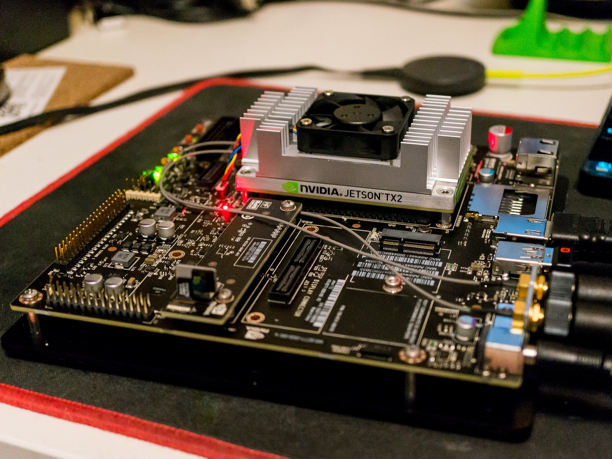 ## Solder the PCA9685 and Razor IMU Pins We have two printed circuit boards (PCBs), that we are working with in this lab. The first is the PCA9685 driver board, which lets us use the I2C protocol in order to send PWM signals to the steering servo and ESC on the Traxxas Rally RC Car. The second, is a PCB for the Razor IMU which is a PCB for an Inertial Measurement Unit. This sensor will give us information about the cars kinematics, such as linear/ angular velocity.

Wiring
While doing the wiring process it is recommended to charge the battery for the Traxxas Rally. This will be necessary to provide power for both the servo and ESC on the Traxxas Rally Car.
Wire the Traxxas Rally to the PCA9685
On the Traxxas rally there will be a box near the front-right tire next to the antenna. This is the receiver box. You need to unscrew the four corners of the box holding it down. When you open the box, you will see two wires plugged into the box. The wires in channel 3 are the PWM for the Traxxas Rally ESC. The wires plugged into channel 1 are for the steering servo. Take the ESC wire and plug it into channel 1 on the freshly soldered PCA9685. Take the steering servo wire and plug it into Channel 0 on the PCA9685.
Wire the PCA9685 to the Jetson TX2
You now need to wire the I2C from the driver board to the Jetson TX2 Carrier board. The pins for the I2C are on the J21 pinouts. This is located next to the power buttons on the Jetson TX2. You can refer to this pinout diagram or to page 25 on the Jetson TX2 Carrier Board Datasheet. Take note of the Bus Number you use. In my case, I used pins 3 and 5 which correspond to bus number 1 on the TX2. This will be important later on when programming the driver board. I also used pins 2 and 6 as VCC and ground for the driver board respectively. After wiring, the green LED on the driver board should be on as long as the Jetson Carrier Board is powered on. To verify the Jetson can detect the driver board is wired properly run the following command:
sudo apt-get update
sudo apt-get install i2cdetect
You can now run the following:
sudo i2cdetect -y -r [bus num]
If you used pins 3 and 5 then the command will be
sudo i2cdetect -y -r 1
You should see an entry for the address 0x40 which is the default address for the PCA9685.
Install QT Creator on the Jetson
The next step is to install QT Creator on the Jetson. This will be used to run some GUI applications to help us find out more about the behavior of the steering servo and ESC motor. Run the following to install QT.
sudo apt-get install qt5-default qtcreator -y
You now need to open QT Creator and go to:
Tools->Options->Build & Run->Compilers
Click the “Add button” and select GCC. In the “compiler path” text box, add the path to gcc /usr/bin/gcc. Now you need to modify the ABI section of the GCC compiler. Change the setting to
custom – arm – linux – generic – elf – 64 bit
Save all your settings by clicking apply.
Now go to click the Kit tab. You should see an error here, with the Desktop kit not having a compiler. Simply create a new kit, (call it JetsonTX2), and you should see that GCC is an option in the compiler options of kit creation. You can now use this kit in order to build QT projects. Finally, make a directory for the car and clone the following repo into it.
mkdir car_workspace
git clone https://github.com/jetsonhacks/jetsonRACECAR.git
There are two projects in this repository. Open up QT and open the projects in the Github repo. Build both using QT. This should create two build directories. One for the setThrottle program and one for the throttleControl program.
Details on PWM
For both the servo and ESC, they each operate at a frequency of 50 Hz. This means that every 20 ms, you will expect to see a pulse. Based on the width of the pulse, the value of the servo or ESC will change. For the steering servo, this corresponds to a change in the angle of the servo. Specifically, a pulse of width 1.0 ms is a servo angle of -90 degrees, a pulse width of 1.5 ms is an angle of 0 degrees, and a pulse width of 2.0 ms is an angle of +90 degrees. In order to translate this to an integer value we can use the following formula. First we calculate the interval for when the servo and ESC expects a pulse. For a motor with a frequency of 50 Hz this is (1000/50) = 20 ms. After that we divide the pulse-width we want by the window we have. In this case if we want a pulse of 1.0 ms then we need to divide by 20 ms. Finally, since each pulse frame is 12 bits, we need to multiply by 2^12 or 4096. If we throw this into a formula we get the following: 1. 1.0ms/20ms * 4096 = 204 2. 1.5ms/20ms * 4096 = 307 3. 2.0ms/20ms * 4096 = 409
However, you may find that these values aren’t exact for both the ESC and the steering servo. In the next part, you will find the range of these values for both the steering servo and throttle using two different GUI programs.
Find the range on the Servo and ESC
After cloning and building the QT projects, you will be presented with two build directories. Navigate to the one for throttleControl on the command line and then do
sudo ./throttleControl
This will open up a GUI application that will allow you to see the results of different PWM values on the cars servos. The reason we need to use sudo is because the program is doing low level control of the GPIO on the Jetson Carrier, and we need to give access to that hardware on the user level, which requires root access. You will now be brought up with a GUI program that allows you to change the PWM values for both the ESC and steering servo. First start by playing with the steering servo, (its an option on the GUI). Find the maximum and minimum values for the steering servo. You can tell you’ve reached a max when incrementing (or decrementing) the values causes the servo to make a small whining noise. Note these down as it will be important for the code.
You now need to find the PWM values that turn the car motor on. Specifically, you will need to find the values that push the car forward and backward, as well as their respective maxes/minimums. However, before you do that you need to calibrate the ESC. Close the QT program for now, it will be used again later.
Calibrating the ESC
In order to calibrate the ESC, we need to use the other QT program called setThrottle. Navigate to the build directory for this project and do:
sudo ./throttleControl
This will open up another QT GUI. This will be used to calibrate the ESC of the car motor. In order to calibrate the ESC press the small blue button on the ESC to power it on. Hold the button until the LED turns green and then red. When the LED blinks red once, hit the full throttle button on the GUI. When the LED blinks twice, hit the full reverse button on the GUI. The LED should blink red or green depending on the battery level. When the LED is solid red that means it is armed.
You now need to switch back to the throttleControl program. Increment and decrement the PWM value for the ESC so you know the values when it starts to reverse and go forward. You should also find the upper limit for both forward and reverse values in terms of throttle. This will again be important for your program. You should note the following values: 1. Throttle Reverse Min: 2. Throttle Reverse Max: 3. Throttle Forward Min: 4. Throttle Forward Max:
For me, these values ended up being: 1. Throttle Reverse Min: 295 2. Throttle Reverse Max: 215 3. Throttle Forward Min: 315 4. Throttle Forward Max: 395
You can tell you have hit a min when the wheels are barely turning. You can tell when you hit a max when you start to see arcs in the motor for the RC car.
Making the Car Class
You now need to make the Car class in C++. The Car class consists of two main components. The first is a private variable for the PCA9685 and the second is a private variable for the joystick. This is because these two objects are the only thing used for communication to control the car. The joystick commands will be read using the SDL library. A library for the PCA9685 is already provided for your use. It is up to you to figure out how to use the API calls provided by the library.
Install SDL2
The first step for this phase is to install SDL2. This can be done using the following command in Terminal:
sudo apt-get install libsdl2-dev
You can now include SDL into your C++ files using:
#include <SDL2/SDL.h>
You can link the SDL library to your projects using the following g++ linker flag.
-lSDL2
Controller Mappings for the DualShock 4
The next step is to figure out how to read values from the DualShock 4 using the Jetson over Bluetooth. The first step is to connect the DualShock 4 to the Jetson. You will first need to turn on Bluetooth for the Jetson. This can be done by typing Bluetooth in the Ubuntu search bar, navigating to the Bluetooth settings and turning it on. We now need a way to actually setup a Joystick in Ubuntu. Typically this is done by creating a file with the Joystick info using /dev/input/js[num] where num is the joystick number. Luckily, we can install a driver to help us setup this file and read joystick information from it. Run the following command:
sudo pip install ds4drv
You may get an error saying that you do not have pip installed on your current system. In order to rectify this, run the following commands.
sudo apt autoremove
sudo apt-get update
sudo apt-get dist-upgrade
sudo apt-get install python3-dev python3-pip python3-tk
sudo apt-get install python-dev python-pip python-tk
You should now be able to install ds4drv. ds4drv is a python wrapper that reads in inputs from the DualShock 4 using a driver written in Python. In order to connect the DualShock 4 first start ds4drv in the terminal using:
sudo ds4drv
Then hold the Playstation button and share button on the controller for 5 seconds until the LED on the controller starts blinking white. This will put the controller into pairing mode. You should soon see a message on the Terminal saying the controller is connected, and the LED on the controller should turn a solid blue indicating it has been paired with the Jetson. In addition, there should be a joystick number that pops up when the controller connects. Note this down as it will be important for the code. In order to test the joystick commands are being read properly we can use a GUI program. In terminal run the following.
You should now be able to use the SDL library in order to read the inputs from the DualShock 4. Note the joystick number from the previous section as it will be important to read inputs using SDL2. Refer to the official documentation. There is also a code example on the slides that you can refer to. Refer to this document to the following document to get the DualShock 4 joystick mappings. I recommend mapping the steering servo to the joystick
Sending PWM Commands to the Driver Board
Included in the zip file for the lab are the header and implementation files for the PCA9685. You need to understand this library and learn all its features. Refer to the understanding PWM section of the Readme in order to figure out the types of PWM values you need to send to the car.
After verifying you can send commands to both the ESC and steering servo, you now need to be able to read information from the IMU. Included in the zip file for the lab is a library for the IMU as well as example code. The IMU communicates using I2C. Luckily, the Jetson has 2 I2C buses on the J21 expansion header. So you can connect both the IMU and the PWM driver board. Again, take note of the bus number as it will be important for your code. You need to demonstrate that you can read all values off of the IMU. You can make a simple console program that prints the values of the IMU.
Submission
Your submission for this lab should include the final code to get the car running. This should include a Makefile that includes both a compile and clean command. Both groups will also need to demonstrate they can control both the steering servo and the throttle control using the PS4 controller. In addition, you will need to demonstrate you can properly read values off of the IMU. This will be verified by a checkoff in lab.